
Collimation error and the 2C check
Understand collimation error, Face I and Face II observations, and the role of repeatable inspection in a 2C check.
D
DADI Technical Team
Measurement Fundamentals
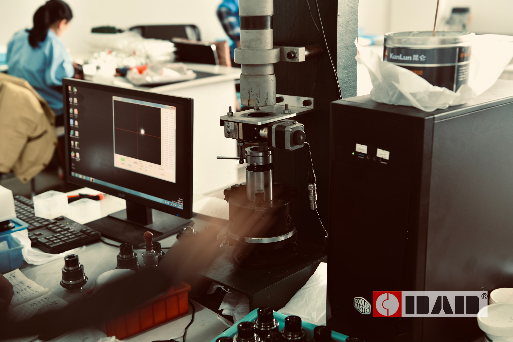
Related factory image: surveying instrument axis inspection at DADI.
SUMMARY
Collimation error occurs when the telescope’s line of sight is not perpendicular to its horizontal axis. Face I and Face II observations support the 2C check, and repeated measurements help assess stability.
On this page
Technical basis: DADI collimator-based 2C measurement and factory standards confirmed by Mr. Ronghua Zhou, together with DADI electronic theodolite production, mechanical adjustment and service inspection experience.
Updated: October 2026
Collimation error arises when the telescope's line of sight is not perpendicular to its horizontal trunnion axis. DADI checks this condition by sighting the same collimator target in Face I and Face II. After allowing for the nominal 180° difference between the two horizontal-circle readings, the Face I reading minus the Face II reading gives the 2C result under DADI's sign convention. The factory acceptance limit is ±10″, and the stricter DADI internal control target is ±5″. These are limits for the measured 2C error, not for the difference between repeated readings.
Key Facts
- Error Definition
- Line of Sight vs. Horizontal Axis
- Inspection Method
- Face Left + Face Right
- Factory 2C Acceptance
- ±10″ Acceptance; ±5″ Internal Target
- Correction Sequence
- Mechanical First, Software Residual
From Detecting 2C Error to Confirming Stability
Level instrument → Face I sighting and set 0° → Face II sighting of the same target → Subtract the Face II reading from the Face I reading and normalize the 180° difference → Check ±10″ / aim for ±5″ → Adjust if needed → Recheck stability
What Is Collimation Error?
The telescope of a theodolite contains a reticle that defines the aiming direction of the instrument. This direction is commonly called the line of sight or collimation axis.
Ideally, the collimation axis should be perpendicular to the horizontal trunnion axis. If this geometric relationship is not exact, the actual direction indicated by the telescope differs slightly from the theoretically correct direction.
This deviation is known as collimation error. In practical theodolite inspection and calibration, it is commonly evaluated through Face Left and Face Right observations and expressed as 2C.
2C error should not be confused with encoder error. An angle encoder may correctly report the rotational position of the instrument while the telescope's actual line of sight still contains a geometric deviation. Complete theodolite accuracy therefore depends on optical alignment, mechanical geometry and electronic angle measurement together.
What Causes Collimation Error?
Reticle Installation and Adjustment
A common source of collimation error is incorrect positioning of the telescope reticle. If the reticle is not properly installed or adjusted, the line of sight may not remain exactly perpendicular to the horizontal axis. Because the reticle defines the direction used by the operator to sight a target, even a small positional deviation can influence horizontal direction observations.
Mechanical Changes Inside the Telescope
The focusing lens moves during telescope focusing. Its movement depends on the mechanical slide and guide structure inside the telescope. If the machining accuracy or fit of the slide and guide structure is insufficient, movement of the focusing mechanism can introduce a small change in the optical relationship. Temperature changes can also cause small deformation of mechanical components.
Transportation, Vibration and Impact
Electronic theodolites contain precisely aligned optical and mechanical components. Rough transportation, strong vibration, sudden temperature changes, impact or a drop can cause very small internal displacement or deformation. These changes may not be visible from outside the instrument.
Long-Term Use and Material Stress
After long periods of operation or storage, residual stress within mechanical components and assembled structures may gradually release. These small changes can alter the original geometric relationship and contribute to collimation deviation over time.
How Does Collimation Error Affect Angle Measurement?
Collimation error mainly affects horizontal direction measurement.
For a target observed at a vertical angle α, the influence of collimation error on the horizontal direction can be expressed approximately as:
Where:
C is the single-face horizontal collimation error component, approximately one-half of the measured 2C value under the stated sign convention.
α is the target elevation angle measured from the horizontal, not the zenith angle.
ΔC is the approximate horizontal-direction error contribution from collimation at that elevation angle. The sign depends on the adopted observation convention.
As the target moves farther away from the horizontal line of sight and the vertical angle increases, the influence of collimation error on horizontal direction becomes more significant.
The direct contribution of collimation error to the vertical-angle reading itself is relatively small. Its primary importance is the effect on horizontal direction and accurate target sighting.
Why Are Face Left and Face Right Observations Used?
Theodolite observation commonly uses two telescope positions: Face Left and Face Right.
One important reason for observing in both faces is that the influence of collimation error changes sign when the telescope is changed from one face to the other.
- Face Left
- +ΔC
- Face Right
- −ΔC
When properly observed Face Left and Face Right measurements are combined, the two error components have opposite signs and can cancel each other.
This is why two-face observation remains important in precision angular measurement even when a modern electronic theodolite uses an electronic angle-reading system.
How Is 2C Calculated?
For the inspection procedure confirmed by DADI's technical management, 2C is calculated from the ordinary horizontal-angle readings of the two telescope faces. It is not obtained simply by taking the Face II reading alone.
2C = L − (R ± 180°)
Choose the sign according to the horizontal-circle readings. If R is approximately 180° greater than L, use R − 180°. If R is approximately 180° less than L, use R + 180°. Normalize the result to the small signed angle near zero.
L = Face I (Face Left) horizontal-circle reading; R = Face II (Face Right) horizontal-circle reading. The ±180° term compensates for the nominal opposite-face direction and follows the Face I minus the adjusted Face II sign convention confirmed for this DADI inspection.
With L set to 0° and R near 180°, the formula becomes 2C = L − (R − 180°) = L − R + 180°.
In DADI's simplified collimator test, Face I is first set to 0°. Face II is then aimed at the same collimator target. The Face II reading should ideally be 180°, so any small remaining signed difference is the measured 2C value after applying the convention above.
| Face I (L) | Face II (R) | Calculated 2C | Interpretation |
|---|---|---|---|
| 0°00′00″ | 180°00′03″ | −3″ | Within internal target |
| 0°00′00″ | 179°59′56″ | +4″ | Within internal target |
| 0°00′00″ | 180°00′08″ | −8″ | Within factory acceptance; outside internal target |
| 0°00′00″ | 180°00′12″ | −12″ | Outside factory acceptance |
These readings are illustrative calculations, not actual DADI production measurements. All examples use L = 0° and R near 180°, so 2C = L − (R − 180°). For other circle settings, choose the appropriate ±180° branch and normalize any 0°/360° wraparound. The sign remains consistent with the Face I minus adjusted Face II convention.
How Does DADI Check 2C Error During Production and Service?
DADI uses a horizontal collimator as a stable optical reference for inspection and adjustment of theodolite collimation. The collimator target provides a repeatable sighting reference without requiring a physically distant outdoor target.
Mount the electronic theodolite securely and level it carefully.
In Face I, aim precisely at the collimator reference target.
Set the ordinary horizontal-circle reading to 0°.
Change to Face II and sight the same collimator target.
Record the ordinary Face II horizontal-circle reading.
Calculate 2C from Face I minus Face II, with the nominal 180° face difference removed and the angle normalized.
Check the measured 2C against the factory acceptance range, and aim for the tighter internal control range. Repeat observations as needed to assess stability.
DADI 2C Factory Acceptance and Internal Control
Factory acceptance limit: −10″ to +10″ (±10 arcseconds).
DADI internal control target: −5″ to +5″ (±5 arcseconds).
These limits apply to the measured 2C error itself. They are not allowable differences between repeated 2C results. Repeat observations help identify changes or instability, but no numerical repeatability tolerance is asserted here without a separately confirmed specification.
Why Is Repeatability Important in a 2C Check?
A 2C reading shows the instrument's collimation condition at one moment. Several readings taken under comparable conditions can also help indicate whether the optical and mechanical relationships remain stable.
If successive results change substantially, a technician may investigate the reticle, focusing guide, telescope assembly or other sources of mechanical movement. This is particularly relevant after repair, transportation damage or an impact.
The ±10″ factory acceptance limit and ±5″ internal control target must not be used as an invented tolerance for the difference between repeated readings. Any separate numerical repeatability requirement should be specified independently from the 2C acceptance criteria.
How Is Collimation Error Corrected?
Collimation correction at DADI involves two different levels: mechanical adjustment and software correction.
1. Mechanical Adjustment Comes First
When the collimation relationship requires correction, the telescope is first adjusted mechanically.
The position of the reticle is adjusted through its left and right correction screws so that the line of sight is physically brought as close as possible to the required perpendicular relationship with the horizontal axis.
This is the fundamental correction because it addresses the actual optical and mechanical geometry of the instrument.
2. Software Correction Handles the Residual Error
After mechanical adjustment, a small residual collimation error may remain.
This residual amount can then be handled through the instrument's collimation-error setting function. The electronic correction compensates for the small remaining error, particularly during single-face observation.
Mechanical adjustment corrects the physical relationship.
Software correction compensates for the small residual error remaining after mechanical adjustment.
When properly performed Face Left and Face Right observations are combined, the primary influence of collimation error is already cancelled geometrically. Software correction and two-face observation therefore serve different purposes.
Can Software Compensation Replace Mechanical Calibration?
No. Electronic compensation should not be used as a substitute for proper mechanical adjustment.
If the physical collimation relationship has changed significantly, the first step is to restore the optical and mechanical geometry as closely as possible. Software correction should then be used only for the small residual amount that remains.
This distinction is especially important after strong vibration, impact or a drop, because the problem may involve physical movement or deformation rather than only a fixed electronic correction value.
When Should a Theodolite Be Checked for 2C Error?
A 2C check is particularly important after conditions that may affect the optical or mechanical relationship of the instrument.
After rough or prolonged transportation.
After a drop, impact or strong vibration.
After extended periods of use or storage.
When the operating temperature differs significantly from the previous calibration environment.
After repair or adjustment of the telescope or related mechanical components.
When Face Left and Face Right observations show unusual differences.
When angular measurement stability appears to have declined.
Before work requiring higher angular accuracy.
What Should Be Done After a Theodolite Is Dropped?
After a theodolite has been dropped or subjected to a significant impact, a 2C inspection is required. It should not be treated as only an optional precaution.
A single inspection is also not sufficient to determine whether the instrument has returned to a stable condition.
In DADI's service practice, an instrument that has experienced a drop or significant impact is checked repeatedly over a period of two to three days.
Multiple 2C inspections are performed each day.
Results from different observation sets and different times are compared.
The technician checks whether the 2C condition remains stable over time.
The instrument is not judged only by one apparently normal result immediately after adjustment.
This repeated inspection is necessary because internal deformation or stress caused by an impact may not stabilize immediately. A normal result from one measurement does not necessarily prove that the optical and mechanical system will remain stable later.
After a drop, the key question is not only:
"What is the current 2C value?"
It is also:
"Does the 2C result remain stable after repeated checks over the following two to three days?"
Is 2C Error the Same as Encoder Error?
No. They involve different parts of the measurement system.
| Item | What It Relates To |
|---|---|
| Encoder reading | Determining the angular position of the rotating instrument axis. |
| 2C / collimation error | The geometric relationship between the telescope's line of sight and the horizontal trunnion axis. |
An electronic theodolite can therefore have a correctly functioning angle encoder while still requiring collimation adjustment. Diagnosing angular measurement problems requires the electronic reading system, optical alignment and mechanical axis relationships to be considered separately.
Frequently Asked Questions
What does 2C mean in a theodolite?
2C is a practical value used to evaluate horizontal collimation error through Face Left and Face Right observations. It reflects the deviation caused when the telescope's line of sight does not maintain the correct perpendicular relationship with the horizontal axis.
How does DADI calculate 2C from ordinary horizontal-angle readings?
DADI sights a collimator target in Face I and sets the horizontal-circle reading to 0°. It then sights the same target in Face II. Under the Face I minus Face II sign convention, the measured 2C is the signed difference after removing the nominal 180° change: 2C = L − (R ± 180°), with the sign chosen to account for the 180° difference between faces. For Face I = 0° and Face II near 180°, this is 2C = L − (R − 180°). Normalize the result around zero.
What are DADI's 2C acceptance and internal control limits?
The factory acceptance limit is ±10″. DADI sets a tighter internal control target of ±5″. Both refer to the actual measured 2C error, not to the spread between repeated tests.
Does 2C mainly affect horizontal or vertical angle measurement?
Its main influence is on horizontal direction measurement. The effect on horizontal direction becomes more significant as the vertical angle of the observed target increases.
Can Face Left and Face Right observations reduce collimation error?
Yes. The primary collimation-error component appears with opposite signs in the two telescope positions. When the two observations are correctly combined, these opposing components can cancel each other.
Can software replace mechanical 2C adjustment?
No. Mechanical adjustment should first restore the telescope geometry as closely as possible. Software correction is then used for the small residual error remaining after the physical adjustment.
Why does DADI repeat the 2C measurement?
Repeated readings help DADI evaluate the stability of the optical and mechanical system rather than relying on one observation. This repeatability check is separate from the ±10″ factory 2C acceptance limit and the ±5″ internal control target; those two limits apply to the measured 2C value itself.
Must 2C be checked after a theodolite is dropped?
Yes. After a significant drop or impact, 2C inspection is required. DADI does not rely on a single check. The instrument is inspected repeatedly over two to three days, with multiple measurements performed each day to confirm that the optical and mechanical system remains stable.
Can a dropped theodolite be unstable even if there is no visible damage?
Yes. Internal optical or mechanical components can shift or deform by very small amounts that are not visible externally. These changes may still affect collimation and angular measurement stability.
Related DADI Technical Resources
For a broader explanation of how an electronic theodolite determines angles, see How Does an Electronic Theodolite Measure Angles?
For information about DADI's inspection of mechanical axis components before assembly, see Inside DADI Factory: Horizontal and Vertical Axis Inspection
For an overview of DADI's theodolite development, manufacturing, testing and customization capabilities, visit Electronic Theodolite Manufacturing at DADI
For the wider factory inspection workflow, see How Is an Electronic Theodolite Calibrated and Inspected Before Shipment?
Discuss your measurement requirements.
Contact DADI for instrument selection, technical documents or a specialized application.